History part 2 - First iteration
This post is translated version of my original article to finnish Amiga magazine SAKU from December 2002 which can be found from here: http://www.amigazone.fi/saku/41/osastot/sekalaiset/eriamiga.html
How it all started
The idea to change the casing begin in summer 2000 when I bought my current Amiga. A1200 setup was built into small IBM tower casing which was functional but not so pretty to watch. I decided to start it slow by buying a fitting tower case when I could find one that wouldn't be too expensive.
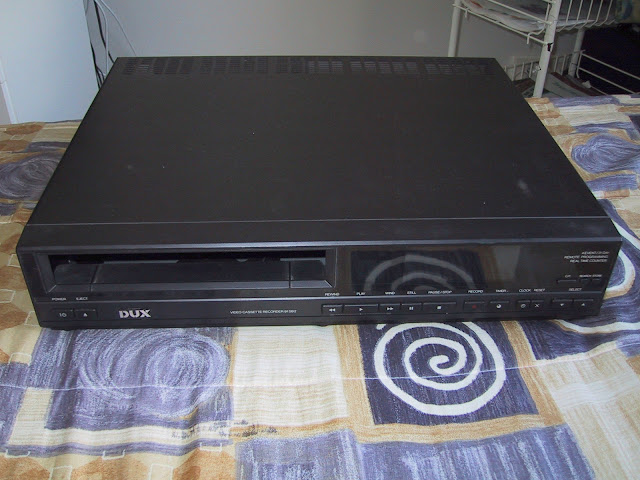
Time went by I hadn't seen a case that would be appropriate. In spring time 2002 I got another idea. A friend of mine told me how he had seen a project in internet where a PC was built into HiFi casing for home theater usage. In the next morning I took a meter and begin to study the possibilities. A1200 with Blizzard 1230-IV combination was about 41 centimeters long so they would fit in 42 cm wide casing. Other minimum measurements were 9 cm for height and about 35 cm deepness. It took time to find a casing like that so in the mean time I did buy an old AT max sized tower case and desktop AT case. Finally I found a DUX branded VHS recorder from local TV&Radio service that fulfilled my size requirements.
Let the building begin
The first task was to take all the stuff out from the case. That was a pretty easy task as was taking apart the front panel's buttons and other stuff. I also took out the Amiga motherboard so that I could do more measuring and test fit the parts in to the new home. I ordered Lyra keyboard adapter, 90 degree angle PCMCIA adapter and AmigaOS 3.9 from Gentle Eye. (Finnish Amiga dealer back then) I had already earlier bought another PCMCIA 90 degree angle adapter.

New ideas
As I was about to buy a TV I decided to add Scart connector for RGB video. But as only one of the TV's two Scart connectors would support RGB video I needed another method to deliver the video to TV as DVD-player would occupy the RGB Scart in the future. In quality wise the next step down from RGB would be S-Video so I started to study possibilities to add one to my Amiga as the quality of composite video wasn't attracting. As the CD32 which is based on A1200 had a S-video connector it shouldn't be impossible to have it in A1200 also. I did find instructions from internet how to modify A520 TV-modulator to have S-video output. But I didn't have one and on the other hand it would take too much space in the casing. In addition Amiga's video port was already occupied by my scan doubler.
After couple days of surfing around internet I found something. A1200 encoder chip was same that was in 8-bit Sega Master System 2. I also found datasheet for the chip although it was in japanese. S-video modifications were already made for SMS2 and I found a page that had instructions for it. Those instructions did say that it wasn't tested because the author didn't have a TV with S-video support. But I checked the correct pins from the datasheet and decided to try my luck.

The mod was pretty easy. A1200 uses Sony CXA1145M decoder which is the chip U12 in the motherboard, close to the RF-modulators shield. Y signal (luminance + sync) is pin 16 and C signal (chrominance) is pin 15. All you need is 75 Ohm resistors and 200 microfarads electrolytic capacitors, plus side on the encoder legs. I attached the ground signals to each other and soldered them to shield of the RF-modulator. The components I just attached to small piece of plastic as I didn't hade perf board at that moment.

Four pin female minidin connector was attached to the end of the cable in the following way. Pin 1 is Y ground, pin 2 is C ground, pin 3 is Y and pin 4 is C. And it was working quite fine. With PC's TV expansion card the picture was in colors and pretty sharp. However the contrast fluctuated depending on the brightness of the picture. Luckily this was happening only with TV-card as the picture is stable with real TV. The image is much sharper than with composite signal, but has a bit more noise compared to RGB-signal.
In addition I made Scart-connector that provides RGB-signal. I made the initial connections with instructions I found online. However, with the first try there was no picture in TV. I checked the connections but I couldn't spot any flaws. I decided to try another instructions based on Saku #16. But again there was no picture in TV just mess of colors. After long checking and thinking session I realized that the sync signal should be connected to different pin compared to the instructions. The difference was that I wasn't making a cable but a connector for Scart cable to attach. That means that I need to connect csync to pin 19 instead of pin 20.

After fixing that error the picture was fine in TV. My Scart connector shares the video port of Amiga but fortunately it doesn't seem to affect the picture quality even when connecting TV and display at the same time.
Building continues
All the following parts were to be fitted in the case: motherboard, turbo card, hard disk drive, floppy drive, external floppy drive with its controller board, CD-ROM drive, PCMCIA network card and power supply. When I put all those in the case at the same time it started to look quite crowded there. I had to remove the casing of the power supply because its height and depth.
Small warning should be also given. Power supply has quite big capacitors inside, so it's better to let them discharge before putting your fingers even close to those. I used following method: When I shut down Amiga I took off the power cable and then switched the power switch back to on-position. Usually fan moved a bit and then after waiting a little bit more I could hear the discharge of some capacitors. Only after that I started to work with the power supply.
I used Dremel to cut and modify the plastic parts of the case. Already in this phase some grinding wheels was used to end of their life. After cutting the aluminium parts the count was already over ten wheels. I took almost all of the plastic away from the front panel just leaving the edges so that I could attach the aluminium sheet to it. Also back panel had quite a heavy modifications. Aluminium plate would be used in it also.
When the case was modified to its minimum it was again time to fit the parts into it. And every part fit well. Well not actually too well but fitted anyway. I was planned motherboard to the bottom front side, disk drives and CD-ROM above it and power supply and hard disk the the back of the case. I started then to think that how I can make the drive "hover" above the motherboard. For a while I changed the plan so that the drives would be at the bottom and motherboard would be above them. But after some thinking I abandoned that idea because there wouldn't be enough airflow in the case. So I returned back to plan A.

I then realized that I could make stands for the drives from the aluminium sheet. So I took some cardboard and started to plan the stands using it. When the parts were planned I took a hacksaw and cut some aluminium sheet. It took some time to have it right but in the end I was happy with the result.

I designed the front and back panel also using cardboard first and then using Dremel and power drill. The end result was ok, I had some minor flaws here and there but I got them hidden quite well in the sanding phase before painting the case.
I had to saw the regulator heat sink a bit so that it would fit in the case. When everything was fitted in the case it was time to test the setup. Everything else was ok, but for some reason the image in the VGA display was black and green. I shut down the Amiga and checked the connections. The reason was loos grounding wire and was touching the pcb of the scan doubler, whoopsie! Luckily nothing was fried and when I removed that wire the image was back to normal, at least almost. There was some short horizontal lines in the image and every now and them image went black. At the same time image was fine in TV when using RGB or RF cable so the problem had to be in the scan doubler. Later I noticed that a capacitor had got some problems from all the bending and also one trace was broken in the scan doubler's connector pcb. I fixed those with new component and some wire. Horizontal lines were gone, but the image went black still from time to time.
Bang!
I noticed later the image went black only when the power supply was inside the case. If I took it out of the case the image was stable. Also if I lifted the power supply few centimeters up the image was fine. But I didn't have extra space in the case for that. So I had to try to get rid of the problem with other ways. I made a little shield from the aluminium to cover the video connector but it helped only a bit. Next step was to create a partial casing for the power supply that was also made of aluminium sheet. It covers the power supply from below, from the side of the motherboard and also a bit from above.
Back to testing. I connected the power cable and then connected the cable to main socket. BANG! Apparently everything wasn't ok. A resistor exploded from the power supply. Either there was too little insulation between the pcb and casing or the reason was because the casing was connecting to the regulator heatsinks. Later I noticed that latter was the real reason as the voltage between ground wire and heat sink was about 100V when I measured it while Amiga was running.

Fortunately there was tiny bit of the resistor left from where I could read the correct value and buy a new one. And the power supply was working again after I changed the resistor. That was fortunate as if I would had to buy new power supply the holes in the back panel wouldn't probably be at correct locations. In the other hand I wouldn't like to take a part a brand new power supply.
I made the insulation better from below and above power supply and noticed that it wasn't still enough to get rid of the disturbance. The image was still flickering, although it was ok after cold boot, but after the Amiga had been on for 20 to 30 minutes the image started to flicker again. I also noticed that NTSC resolutions didn't have that problem, only small parts the image was having some kind of waving or flickering every now and then. There was no such problems in Workbench screens. So probably the mains 50Hz was causing the problems of PAL picture with scan doubler. Solution would be to change the positions of hard disk drive and power supply, but it has to wait at least to next summer because the image is fine with TV and its every connection. Desktop is fine with the monitor as it uses higher resolution with higher refresh rate.
Final assembly

If the case was looking crowded already earlier it was looking that there would be no space at all after adding all the cabling. Slicing the flat cables to ~10 wire bunches helped a bit. I also tried to organize the cables such a way that air could flow as good as possible.
I made small 3mm holes for the LEDs. Power, floppy and disk drive LEDs I connected directly to the motherboard via 180 Ohm resistors. I changed the external floppy drive's LED to a one with leads and I also modified the CD-ROM drive so that I connected another LED parallel to its own one. That is the reason it blinks a bit dimmer that others but I didn't want to remove the SMD LED from the CD-ROM drive. I used hot glue to attach the LEDs behind the front panel and there's a thin plastic sheet between the LEDs and the holes. I replaced the Lyra wiring with longer ones and had to bend the connector to get it to fit under the CD-ROM drive.

In the back panel there was power supply connectors, serial, parallel and external floppy connectors. Scart connector, S-Video connector, scan doubler's SVGA connector and RCA connectors for audio, RF signal and composite video. I also made a hole for the Ethernet cable and a bigger one for a 6 cm fan. I connected the fan with 100 Ohm potention meter so I can control the speed of the fan from the back panel. Ethernet connector I made from cable extender which I took a part and solder a short wires that were used to connect it to the PCMCIA card's connector part.
When I had painted the aluminium plates and connected the connectors to the back panel it was time to attach the panels to the case. At that point I noticed one design flaw. RCA connectors were a bit too high and were touching the hard disk drive stand. I fixed it with enough amount of electrical tape. I shall fix it better when I switch the places of power supply and hard disk drive. First I tried to glue the aluminium plates with hot glue but it wasn't sticking properly so I had to use another method. I bought water-soluble contact glue which at least promised to glue metal and plastic. And that was doing the job properly.

I also made a small aluminium plate to the CD-ROM drive's tray and attached it with super glue and some fitting plastic part. In addition I used a lot of hot glue between the parts so it would hold it properly. The aluminium plate is pretty loose compared to the hole in the front panel, but so is the attachment of the CD-ROM drive to the case so it is actually good that there is some tolerance. Also as I painted the CD-ROM drive's face plate also black the gap isn't too visible. I put six rubber feets to the bottom of the case and four pieces of chromed pipe which made the case look more like HiFi device. Just stickers added next to the connectors and the project was now done.
Summary
After all the work I'm happy that I started this project. Now my Amiga may reside with the AV-receiver, CD-player etc. It helps a lot when finding a place for it and also makes it easier to use the Amiga. Also now the keyboard and controllers can be changed quickly from the front panel. And with the RGB and S-video connectors it is nice to play for example Sensible Soccer with the 32 inch widescreen tv.
The negative side of the project is the PAL image flickering when using scan doubler. It is fixable though and probably I will fix it in the near future. Also now the expanding of the Amiga is quite limited so I cannot and something like PCI bus card. But with the current usage patterns I don't miss such things much. Turbo card can be changed to more powerful if needed, although you need to use quite much time to achieve it. I spent 220 euros to the project from which the PCMCIA adapters, Lyra and AmigaOS 3.9 was around 160 euros. To the case it self was around 60 euros.


Comments
Post a Comment